Multi purpose industrial receiver.

The Quartet is a laser ultrasound instrument based on our patented MCRQ (Multi-Channel Random Quadrature) technology. Developed with support from the National Science Foundation and NASA, the Quartet was designed to be compact, robust, and highly sensitive, even on rough surfaces—overcoming traditional limitations of optical interferometry. Its detection scheme employs an enlarged aperture and detector arrays to capture an unparalleled number of speckles, maintaining high sensitivity without needing stabilization. The system accommodates both visible and IR photodiode detectors and features a versatile, fiberized optical head for diverse measurement conditions. With an internal laser power of up to 3W, the Quartet is ideal for industrial applications, including in situ weld and additive manufacturing inspections. Its advanced capabilities extend to detecting disbonds in composite materials, monitoring weld quality, measuring material thickness, and visualizing wave propagation in complex shapes.

FEATURES

Robust & Versatile
Because the technology does not require control over the length of the optical path within the system, the Quartet is not subject to stability issues common to most long cavity and path-stabilized interferometers. It does not require high accuracy optical components or positioning, making it exceptionally rugged.

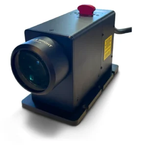
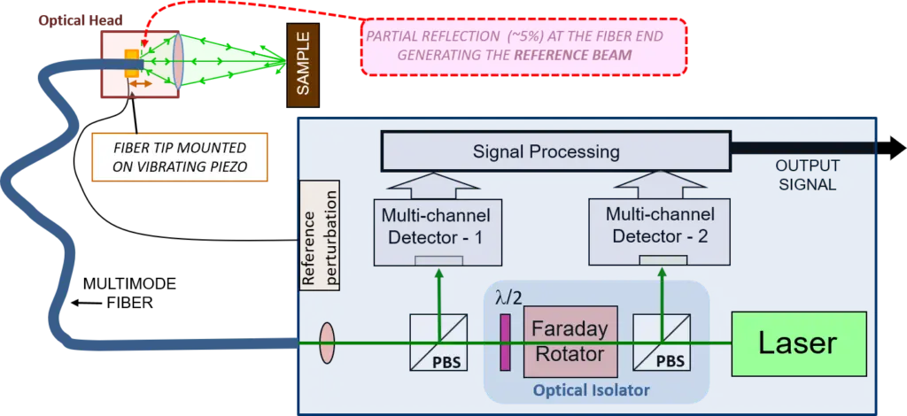
Fiberized Optical Head
A relatively small and versatile fiberized optical head is easily mounted to fit a variety of measurement conditions and can be set-up for a wide-range of stand-off distances. Its front lens can be easily changed or replaced if necessary.

Measurement Precision
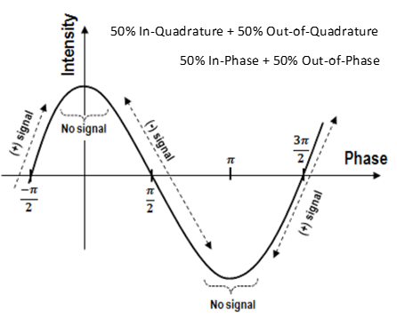
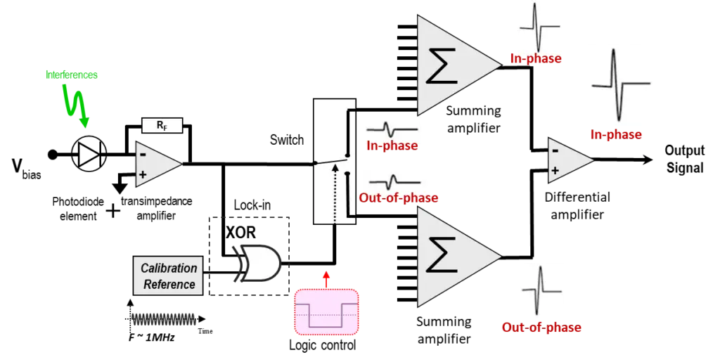
The Quartet produces an analog signal that is proportional to surface displacement.

High Sensitivity on all Surface Types and Materials
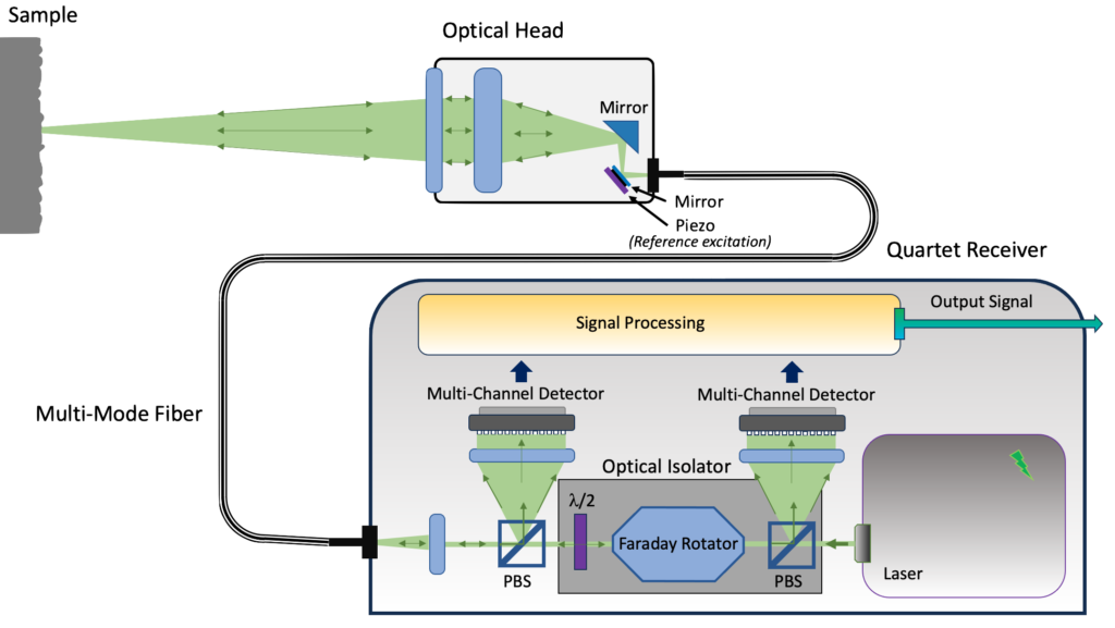
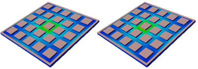
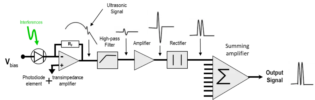
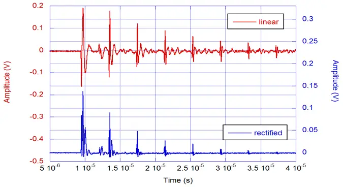
Thanks to its multiple detectors and high transmission optics, the Quartet accomplishes efficient light collection and thus, high sensitivity. This continues to be true when the system is fitted with a moderately powerful laser thanks to low noise detectors and electronics. By detecting and processing many speckle interference signals, the Quartet achieves a stable demodulated signal even when processing a highly speckled beam. This means that it can perform measurements on any kind of surface, including rough, porous, rusted or mirror-like surfaces.

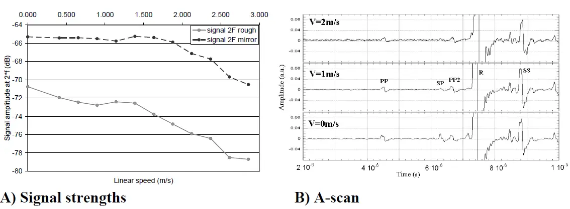
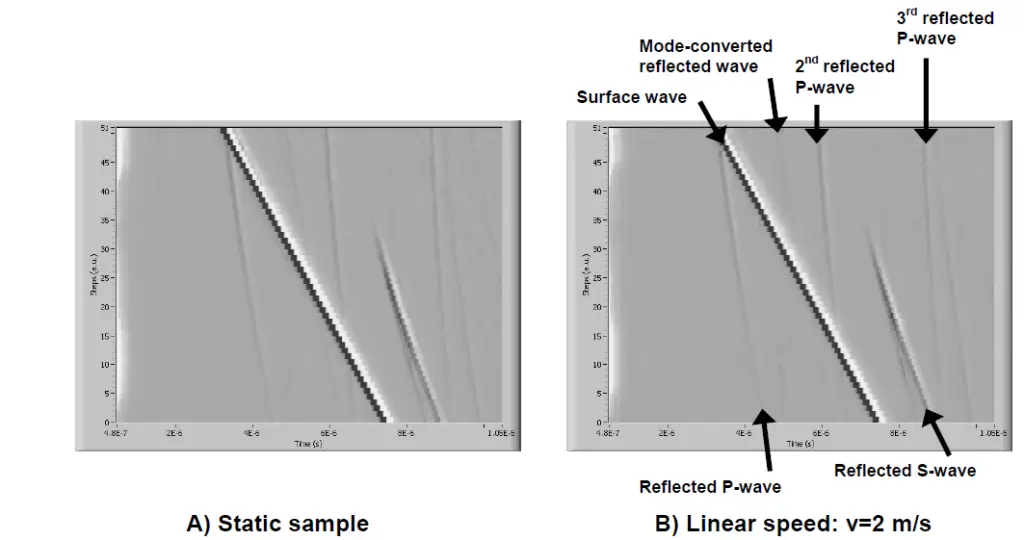
Inspection on Rapidly Moving Objects
Streamlined electronic processing allows the Quartet to perform single shot measurements on fast-moving objects, at speeds up to meters per second.

Not Wavelength Dependent
The Quartet can be fitted with a range of internal laser wavelengths ranging from visible to infrared.
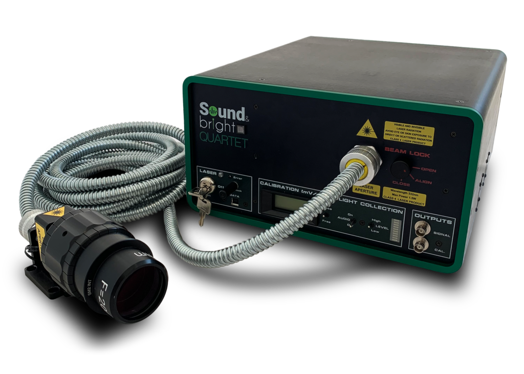
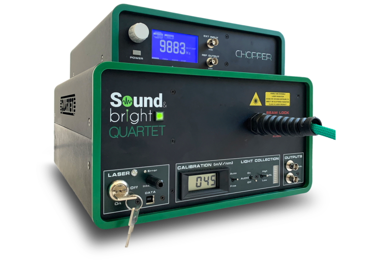
Signal Indicators
Incorporated within the system are visual and audible signal indicators designed to help the user optimize their measurement setup. The Quartet also includes an internal calibration signal allowing for a calibrated output at 100mV per nanometer of displacement.

Beam Chopper

The beam chopper is an optional feature which allows the system to be used on materials with poor heat conductivity, such as plastics or carbon fiber materials without damaging the surface. A perforated disk synchronized with the generation laser “chops” the beam at a regular interval in order to prevent the sample from being exposed to continuous laser power. This feature does not affect the quality of the signal as it allows the laser to be used at full power, in contrast to alternative solutions such as using continuous but low laser power systems. Once installed, the chopper can be turned on and off to suit the application. This upgrade is compatible with new generation Quartets and is easily installed by replacing the top cover of the system.

Motorized Optical Head

The motorized optical head features a high-precision lead screw (TR82), facilitating a linear displacement of 2mm per revolution for  fine focus control.

To ensure maximum operational flexibility, the optical head supports dual-mode functionality:

  • Remote Digital Control: Seamlessly interface with a computer for automated or long-distance adjustments.

  • Manual Override: Utilize the integrated external command for direct, tactile positioning.

TECHNICAL SPECIFICATIONS

TECHNOLOGY

Multi Channel Random Quadrature

DETECTION

Out-of-plane

CONFIGURATION

Optical FIber

INTERNAL LASER POWER

Up to 3W

BEST NESD (out of plane motion)

2.10-6 nm/Hz1/2

DETECTION BANDWITH

Up to 100MHz

DIMENSIONS (L*W*H)

400*325*188 mm

WEIGHT

9Kg

ELECTRICAL REQUIEREMENTS

110V/50Hz – 220V/60Hz


TECHNOLOGY

The Quartet receiver combines the advantages of homodyne interferometry with the benefits of multi-detector technology. The beam reflected by the sample’s rough surface is comprised of many speckles. The multi-speckled signal beam is combined with the reference beam and focused on 50 photo-detectors. Each detector collects a few speckles and delivers a homodyne signal.

Each homodyne signal is processed in parallel using a patented signal processing architecture. The signal processing is based on a “random quadrature” demodulation scheme which takes advantage of the random phase distribution inherent to speckle light. 

Rational

The idea behind Multi-Channel Random Quadrature was to devise a laser-ultrasound technology with a robust, compact design and a large depth-of-field capable of functioning effectively in a wide range of environments without loses in sensitivity, including on rough surfaces. With support from the National Science Foundation and NASA, we developed the Quartet. By collecting and processing a multitude of speckles, the Quartet is fully functional in environments which would otherwise be unsuitable for most other receivers and can perform measurements on all surface types — from mirror-like to rough surfaces.

Multi Channel

Two detector arrays of 25 elements each allow the Quartet to collect more speckles than a standard receiver, which in turn translates to high sensitivity. To put it another way, employing MCQR technology is equivalent to using 50 Michelson interferometers in parallel.

The Quartet does not need to be stabilized as it relies on the random nature of speckles. Statistically, the speckle phase has a uniform distribution, meaning that it is 50% in-quadrature and 50% out-of-quadrature. The out-of-quadrature components don’t contribute to the signal, which is why we use 25 photodiodes on two detectors. Demodulation is required for both the in-phase and out-of-phase signals.

Optical Design

A laser beam generated by the internal laser passes through multiple optics within the receiver before being focused into a multimode fiber. At the end of the fiber, around 4-5% of the light is reflected back towards the receiver due to a natural optical phenomenon while the rest is focused onto the sample. The diffuse light reflected by the sample surface is collected by a large lens located at the front of the optical head, maximizing the quantity of speckles gathered for signal processing. The speckled beam then travels back through the optical fiber, interfering with the 4-5% partial reflection previously mentioned. It is important to note that the light polarization components are scrambled while traveling back through the multimode fiber. Once back in the system, the beam travels through a first Polarized Beam Splitter (PBS) which isolates the vertical polarization component and is in turn directed towards one of the two detector arrays. The rest of the beam travels through an Optical Isolator, which consists of a Faraday rotator and a PBS. This second PBS then sends the vertical (previously horizontal) component of the returning signal-beam back towards the second Multi-Channel Detector. Every signal from the photodiodes will be processed in parallel by an electronic demodulation.

Rectified Demodulation

Because of the random nature of the phase of each of the 50 signals detected, the quartet is designed to perform signal rectification without consideration of phase. The streamlined electronic processing allows the Quartet to perform single shot measurements on fast-moving objects. Rectified Demodulation is also effective at rejection of background noise vibration.

Rectified Demodulation alone has a few downsides: it has a high-frequency and small-displacement limitation, and the direction of displacement is unknown. Therefore, the Quartet also uses Linear Demodulation.

Linear Demodulation

Linear Demodulation is a similarly compact multi-channel architecture, but with a demodulation scheme that yields an output signal proportional to the wave-displacement. It is composed of a transimpedance followed by a logic control which detects the signal phase and switches between two summing amplifiers: one receives the in-phase and the other the out-of-phase signals. Lastly, both phases of the signal pass through a differential amplifier.

PATENTS.

Patent US7978341

Multi-channel laser interferometric method and apparatus for detection of ultrasonic motion from a surface.

Patent US7894338

Interferometric method and apparatus for linear detection of motion from a surface

Patent US7729881

Laser intensity noise rejection for interferometric apparatus

APPLICATIONS

Our systems have a multitude of potential applications. Listed below are a just few brief descriptions of feasibility studies done using our receivers. If you have any questions regarding applications, we would be happy to lend our expertise to your problematic.

Thanks to a short response time, the Quartet features the ability to perform highly sensitive measurements on moving samples. To demonstrate this capability, we performed experiments on a rotating disc composed of aluminum, 9 mm thick with a diameter of 130 mm. One side had a natural (reflective) finish while the other was sandblasted to create a uniform light-scattering surface.
The signal is first generated by a piezoelectric mirror continuously exiting at f=1.6MHz in the reference path. The signal amplitude is measured at 2f=3.2 MHz (Fig. 1A), because the rectification generates the second harmonic. There is almost no influence on the reflective side below 2 m/s, and then the signal drops slightly (about 5 dB) between 2 and 3 m/s. On the scattering surface, the signal begins 5dB lower than the reflective surface because less light is collected. The drop appears at a lower linear speed, but the signal is still detected. An example of pulse-echo LBU signals recorded with an offset between generation and detection is shown below.

B-scans were performed in a pulse-echo experiment on the scattering side with either the sample at rest or moving and scanning of the generation laser source. The linear speed at the point of detection was 2 m/s. The first three reflected P-waves were detected, as well as the surface wave, the first reflected shear wave and the converted wave (SP). This demonstrates the ability of the interferometer to process a signal even on rough,fast moving samples.

Linear Demodulation is a similarly compact multi-channel architecture, but with a demodulation scheme that yields an output signal proportional to the wave-displacement. It is composed of a transimpedance followed by a logic control which detects the signal phase and switches between two summing amplifiers: one receives the in-phase and the other the out-of-phase signals. Lastly, both phases of the signal pass through a differential amplifier.

This experiment was carried out in a pulse echo configuration using the Quartet with rectified demodulation, a beam chopper and a generation laser on two composite layers bonded together. The goal was to detect disbonded areas between those two layers. Both B-scan and C-scan were realized. The B-scan below clearly shows the early arrival of the waves due to non bonding between the two layers. The C-scan was generated by displaying the time of arrival for the first echo.

In-process monitoring of weld quality by continuous monitoring of the ultrasonic emission (UE) generated by the welding process during high-speed laser welding. In this case we want to evaluate the welding quality during high speed laser welding. We use the rectified demodulation and monitor the intensity of the ultrasonic emission generated by the welding process. As shown below, the intensity of UE clearly increases where defects appear.

The following scan on a electrical ceramic high-power insulator was performed using the quartet integrated within a Tsukuba Technologies LUVI (Laser Ultrasonic Visualizing Inspector) solution. The setup allows for rapid scanning of a complex shape, while displaying the propagation of ultrasonic waves using a sophisticated visualization software. The LUVI detects at a pulsed generation beam at a fixed location and uses the reciprocity principle of sound propagation. Mirror scanning and a high-repetition rate laser enables high-speed inspection of an object with a complex shape, while visualization of ultrasonic waves makes identifying defect echoes easy.

In the clip below, the propagation of the ultrasonic wave is blocked by a crack and a reflected wave is subsequently generated.

When propagating through a specimen, the ultrasonic waves carry information about the inner structure. Similarly, when propagating along a surface, the information about the surface quality and surface coatings can be extracted.

Request a Brochure.

Brochure request - QUARTET
Scroll to Top